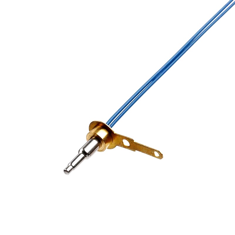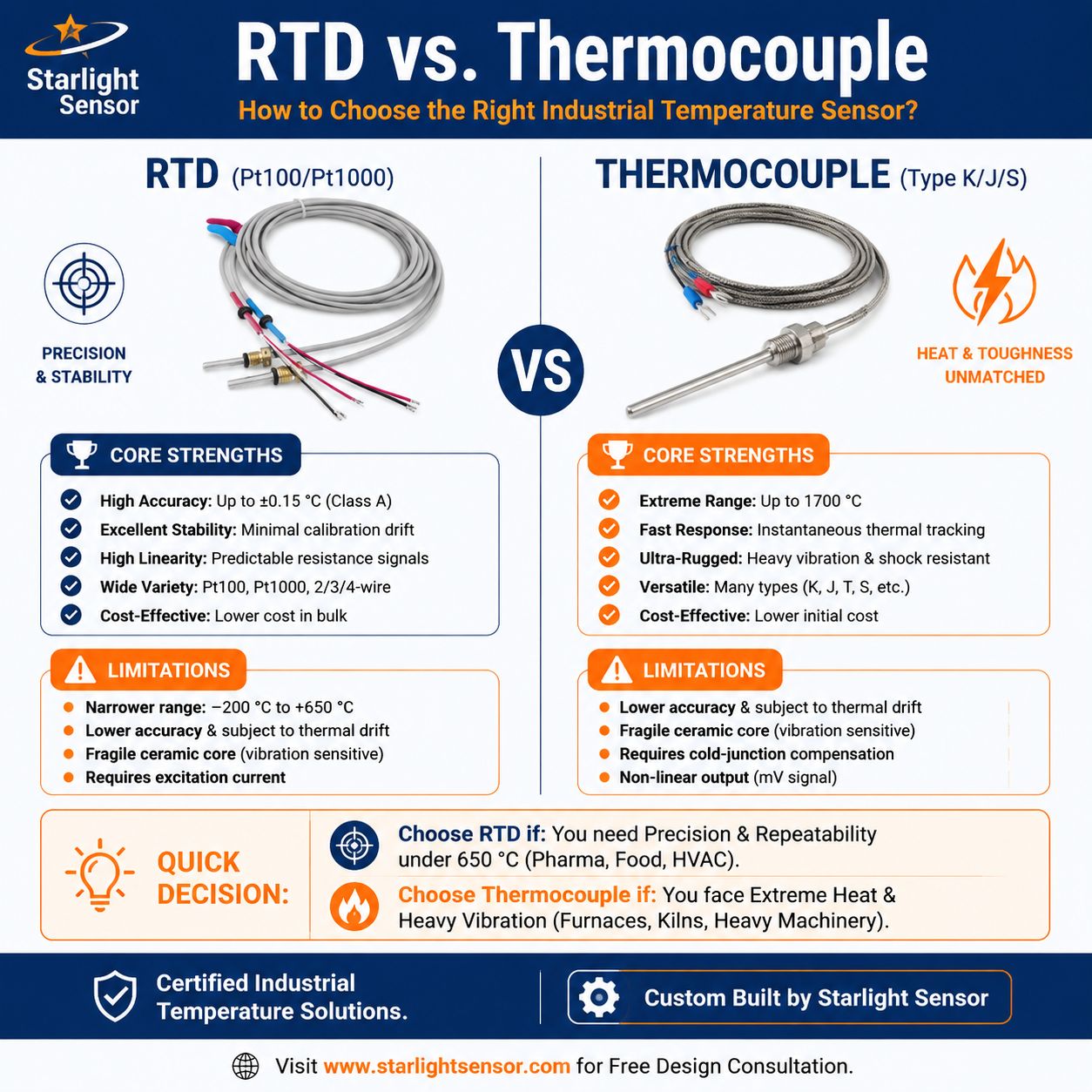
Pt100 and 4–20 mA describe different parts of a temperature measurement system. A Pt100 is a platinum RTD sensing element whose resistance changes with temperature. A compatible temperature transmitter reads that resistance and converts the configured temperature range into a 4–20 mA signal for a controller, PLC, or monitoring system. The Pt100 element itself does not directly output 4–20 mA.
For OEM projects, keep the probe assembly and signal-conditioning requirements clear from the start. The correct choice depends on the sensor input, wiring, temperature range, transmitter configuration, and receiving instrument.
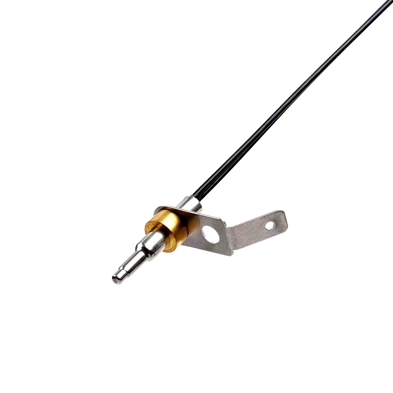
How a Pt100 transmitter provides a 4–20 mA signal
The transmitter measures the Pt100 resistance and maps the configured lower and upper temperatures to the loop’s lower and upper current values. For a common 4–20 mA setup, the transmitter—not the bare RTD probe—generates the current output. The exact input wiring, temperature span, supply, load limits, fault behavior, and calibration procedure depend on the selected transmitter model; follow its documentation.
As one model-specific example, WIKA’s T91.10/T91.20 operating instructions describe Pt100 input and a 4–20 mA output. This is an example of a transmitter arrangement, not a specification for every Pt100 system.
Pt100 and NTC are different sensor inputs
Pt100 RTDs and NTC thermistors use different resistance-versus-temperature characteristics. A transmitter configured for Pt100 should not be assumed to accept an NTC thermistor. Use an NTC input or transmitter only when its documentation supports the required thermistor curve and configuration. For background, see our NTC temperature sensor range and NTC thermistor circuit guide.
OEM selection checklist
- Sensor input: confirm Pt100, NTC, or another supported sensor type and the required resistance curve.
- Wiring: specify the probe lead arrangement and verify that the transmitter supports it.
- Temperature span: define the application’s minimum and maximum temperatures and the intended current scaling.
- Loop and controller: check the transmitter’s supply and load requirements against the receiving analog input and installation.
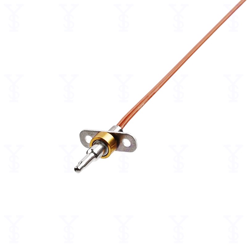
- Probe construction: provide sheath dimensions, cable length and insulation, connector, mounting, and environmental requirements for the sensor assembly.
- Validation: verify the configured endpoints and measurement across the intended operating range using the transmitter’s documented procedure.
Do not select a probe or transmitter from the “4–20 mA” label alone. Confirm that the transmitter input matches the sensor and that the selected range and loop are compatible with the control system.
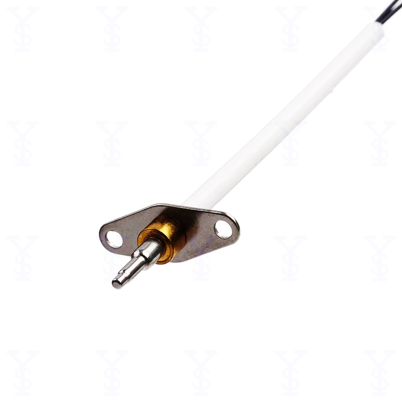
Discuss an OEM temperature-sensing project
Starlight Sensors supplies temperature-sensing components and probe assemblies for OEM applications. Share your sensor type, operating range, probe dimensions, cable and connector requirements, and controller or transmitter input requirements so the assembly can be reviewed against your project. For related products, see our RTD temperature sensor category or temperature sensor range.
Request a quote with a drawing or sample where available, and identify whether your project requires a Pt100 probe only or a separate compatible transmitter.