
How to Read the Vishay NTCLE203E3 Datasheet
The NTCLE203E3 is a Vishay radial-leaded NTC thermistor family. This guide explains how to interpret its published ratings and what an OEM engineer should verify before choosing a part. It is a third-party reference example; this page does not imply that Starlight manufactures or distributes Vishay-branded NTCLE203E3 parts. Always use the current manufacturer datasheet for purchasing and design decisions.
View the Vishay NTCLE203E3 datasheet and compare the exact ordering code against the table before creating a bill of materials.

What the NTCLE203E3 code and table tell you
The datasheet lists multiple nominal resistance values and B25/85 values within the series. For example, its 10 kΩ version is listed with B25/85 of 3977 K; the corresponding ordering number and available tolerances must be checked in the table. The family also includes different R25 and B values, so “NTCLE203E3” alone is not a complete component specification.
Read these fields together:
- R25: nominal resistance at 25 °C, with the specific tolerance listed for the selected code.
- B25/85: a curve parameter calculated between the stated reference temperatures. It is not interchangeable with a B value based on another temperature interval.
- R/T curve: confirm resistance values across the actual measurement range. A single resistance and B value may not describe every required error term or system condition.
- Ordering suffix: verify the resistance tolerance and compliance option against the current ordering table; do not infer them from an abbreviated series name.

Check construction and operating conditions
The Vishay datasheet describes a coated NTC ceramic chip with two tinned nickel leads and radial mounting. It gives the family’s continuous zero-power operating range as −40 °C to +125 °C, with a short-period limit up to 150 °C under the stated conditions. These are component-family ratings, not a guarantee of installed sensor performance. Board layout, lead stress, solder process, encapsulation, airflow, thermal coupling and measuring current can change behavior in an application.
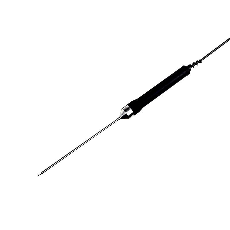
Do not apply a bare component’s limits to a probe assembly without qualification. If a project requires a potted, sleeved or metal-probe sensor, separately define the media, mounting, insulation, sealing and thermal-response requirements. The datasheet specifically cautions that this series is not intended for potting.
Design-in checks for an OEM project
- Match the exact R25, reference temperature and R/T curve to the controller or measurement circuit.
- Evaluate the full tolerance stack, including thermistor tolerance, conversion method, ADC/reference errors, wiring and thermal contact.
- Check self-heating at the actual excitation current and installation condition; use the datasheet’s measurement conditions when comparing published values.
- Review mounting, soldering, strain relief and environmental exposure against the manufacturer’s handling instructions.
- Validate the finished assembly in the intended product across its operating and storage conditions.
For a custom NTC component or probe project, provide the required curve or resistance points, tolerance, temperature range, quantity, installation sketch and qualification needs. See Starlight’s NTC thermistor range or send an OEM inquiry. A custom proposal requires separate engineering review; it should not be treated as a drop-in equivalent to the Vishay part.
Reference
Vishay, NTCLE203E3 NTC Thermistors, Radial Leaded, Accuracy Line, document 29048, revision 29 January 2024. Check the manufacturer site for the latest revision before design release.


