
“1.8 kΩ NTC” is not a complete sensor specification. It may describe a nominal resistance at a reference temperature, but the exact meaning must be confirmed in the supplier’s datasheet. Two thermistors with the same nominal resistance can have different B values, resistance–temperature curves, tolerances, package styles and allowed operating conditions.

What to verify in a 1.8 kΩ NTC datasheet
- Reference resistance: Confirm the stated resistance and reference temperature (often shown as R25), tolerance and measurement conditions.
- R/T curve: Check the B value and the temperatures over which it is defined, or use the manufacturer’s full resistance–temperature table. Do not substitute a curve from another NTC.
- Operating limits: Verify temperature range, rated dissipation or measurement current, maximum voltage, insulation and storage limits from the specific datasheet.
- Mechanical construction: Match bead, chip or probe form, dimensions, lead configuration, encapsulation, mounting and environmental exposure.
- Dynamic behavior: Check the specified response or thermal time constant under the stated test conditions; installation and airflow can change real system behavior.

How to evaluate fit in a temperature circuit
For resistance measurement, an NTC is commonly paired with a known resistor in a divider or bridge and read by an analog input. Select the fixed resistor and excitation so the circuit provides useful resolution across the application’s actual temperature range while respecting the thermistor’s permitted measurement power. Self-heating can bias the reading, especially when the part is small or poorly coupled to the measured surface.
Convert resistance to temperature using the exact component curve. A Beta equation can be a convenient approximation over its stated range when the supplier provides the relevant Beta value. For wider ranges or tighter accuracy, use the manufacturer’s R/T data or model coefficients and validate the complete sensing chain. Check ADC reference and resolution, lead resistance where relevant, noise, open/short detection and calibration against a known reference.

Do not infer application suitability from resistance alone
A 1.8 kΩ value by itself does not establish accuracy, speed, medical suitability, automotive qualification, temperature range or interchangeability. These properties depend on the exact part and finished probe assembly, installation and validation. Review the intended environment and applicable standards with the sensor supplier and system designer before release.
When comparing quotations, provide the target temperatures, resistance curve, accuracy across that range, mounting and probe dimensions, lead/connector details, exposure conditions, annual volume and required evidence. Ask suppliers to identify the exact datasheet revision and confirm which parameters are guaranteed.
Related NTC design resources
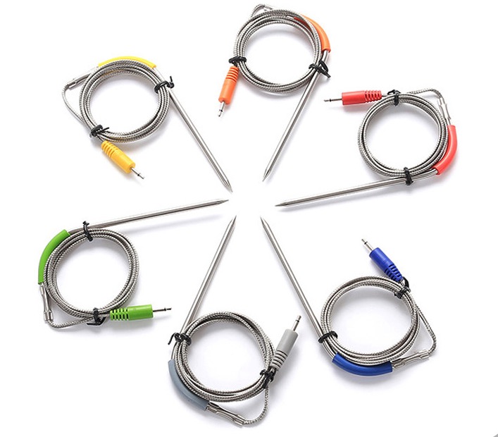
For temperature conversion, see our NTC resistance–temperature curve guide and NTC thermistor C-code guide. For a complete sensing assembly, review our custom NTC probe assembly information. Share the exact R/T curve, operating range and mechanical requirements through our OEM inquiry page for a configuration review.
Technical reference: TDK NTC thermistor overview and selection parameters.


