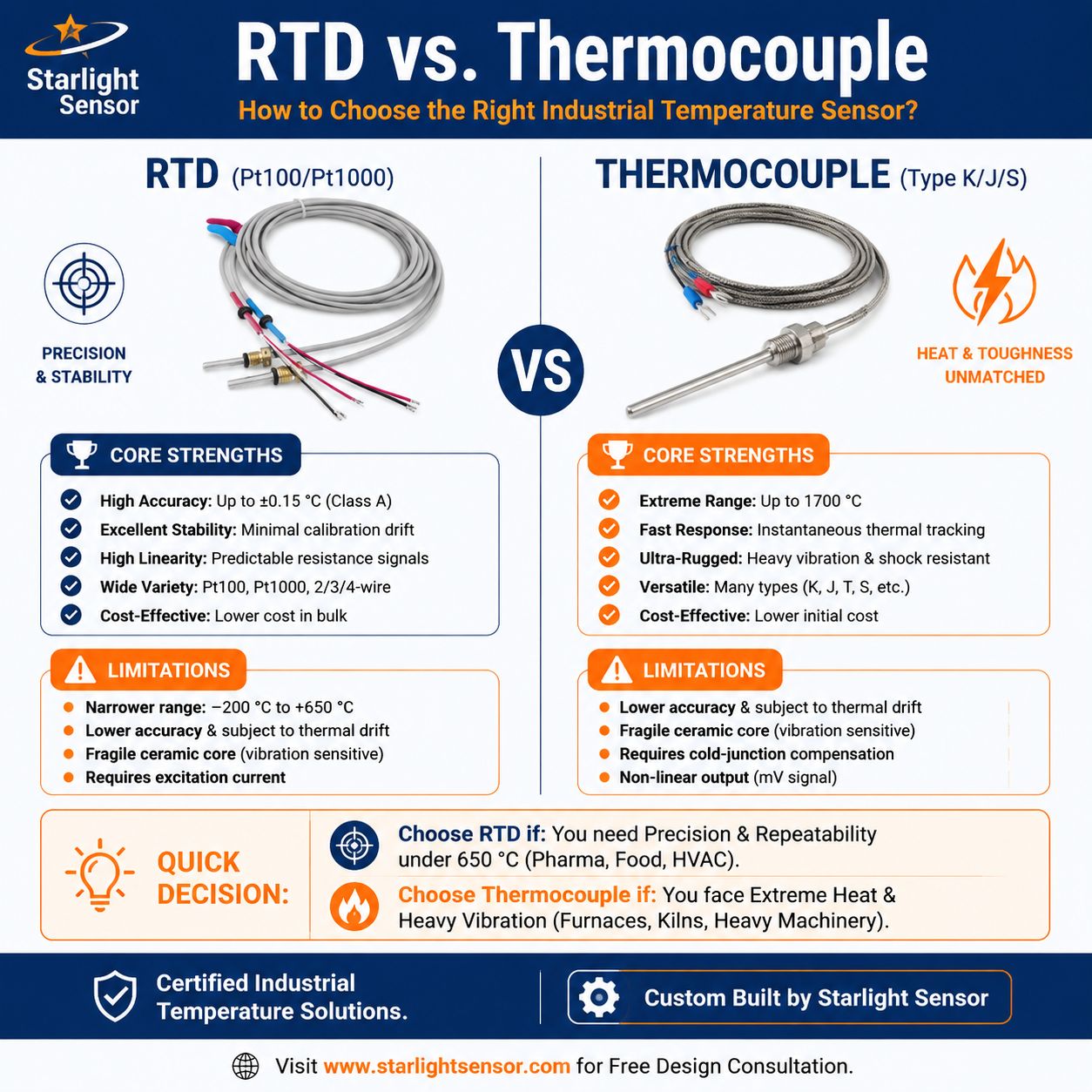
A custom RTD sensor project is easier to evaluate when the mechanical, electrical, and measurement requirements are defined before a drawing or sample is approved. The sensing element is only one part of the assembly: wiring, sheath, mounting, termination, controller input, and the intended measurement location all affect fit and system behavior.
This guide gives OEM engineers and procurement teams a practical specification checklist for a platinum resistance temperature detector (RTD) project. To discuss a specific configuration, send a drawing or application inquiry.
Start with the application and measurement point
Describe what the sensor will measure—such as a liquid, pipe, winding, enclosure, surface, or moving part—and where the sensing element must sit. Record normal operating conditions, expected excursions, response needs, ambient exposure, vibration, cleaning, and service access. A process value measured at the wrong location may not represent the controlled equipment, even if the sensor element itself is within tolerance.
Clarify whether the sensor is used for indication, control, monitoring, or a safety-related function. The responsible equipment designer should define the required limits and system-level validation; a probe specification alone does not establish the performance of an entire product.
Define the RTD element and input
Specify the nominal resistance and reference temperature, the resistance–temperature relationship or standard, the required element tolerance, and the measuring instrument or controller input. State whether the design is PT100, PT1000, or another element and identify the applicable standard revision where required. Avoid using “high precision” as a substitute for a numeric, testable requirement.
Choose a wiring arrangement the instrument supports. Two-wire, three-wire, and four-wire circuits handle lead resistance differently; cable length, conductor material, connector transitions, and input compensation must match the system. Confirm any transmitter or signal-conditioning requirements separately.
Specify the probe assembly
Provide the details that determine whether the sensor can be installed and survive its environment:
- sheath material, outside diameter, wall construction, and usable insertion length;
- mounting thread, flange, compression fitting, bracket, or other interface, including dimensions and sealing needs;
- cable or lead type, length, insulation, routing constraints, and termination or connector;
- expected temperature, pressure, moisture, chemicals, vibration, and thermal cycling;
- response-time or immersion requirements and any limits on self-heating or measurement current;
- quantity, drawing revision, target life-cycle, and change-control expectations.
These inputs support a meaningful design review. They do not imply that every combination is available from a particular supplier; confirm feasibility, materials, and validation evidence against the proposed drawing and product documentation.
Plan sample approval and validation
Agree on acceptance criteria before ordering samples. Depending on the application, the review may cover dimensional fit, terminal identification, resistance at defined reference points, insulation or continuity checks, assembly integrity, and performance in the representative installation. Use a suitable reference and record test conditions, uncertainty, and instrument setup when comparing temperatures.
Validate the complete measurement chain when the application requires it: sensor, cable, connector, controller or transmitter, mounting, and software scaling. Document which party performs each check and how engineering changes are approved. A part-level certificate, when supplied and applicable, does not automatically demonstrate installed-system performance.
What to include in an OEM inquiry
A useful request for quotation includes the application, sensing location, expected conditions, required resistance curve and tolerance, wiring, dimensions, mounting, cable and connector, quantity, drawing, target timing, and required inspection or documentation. If details are still open, label them as open questions rather than assuming standard values. This makes technical review more direct and helps identify missing inputs early.
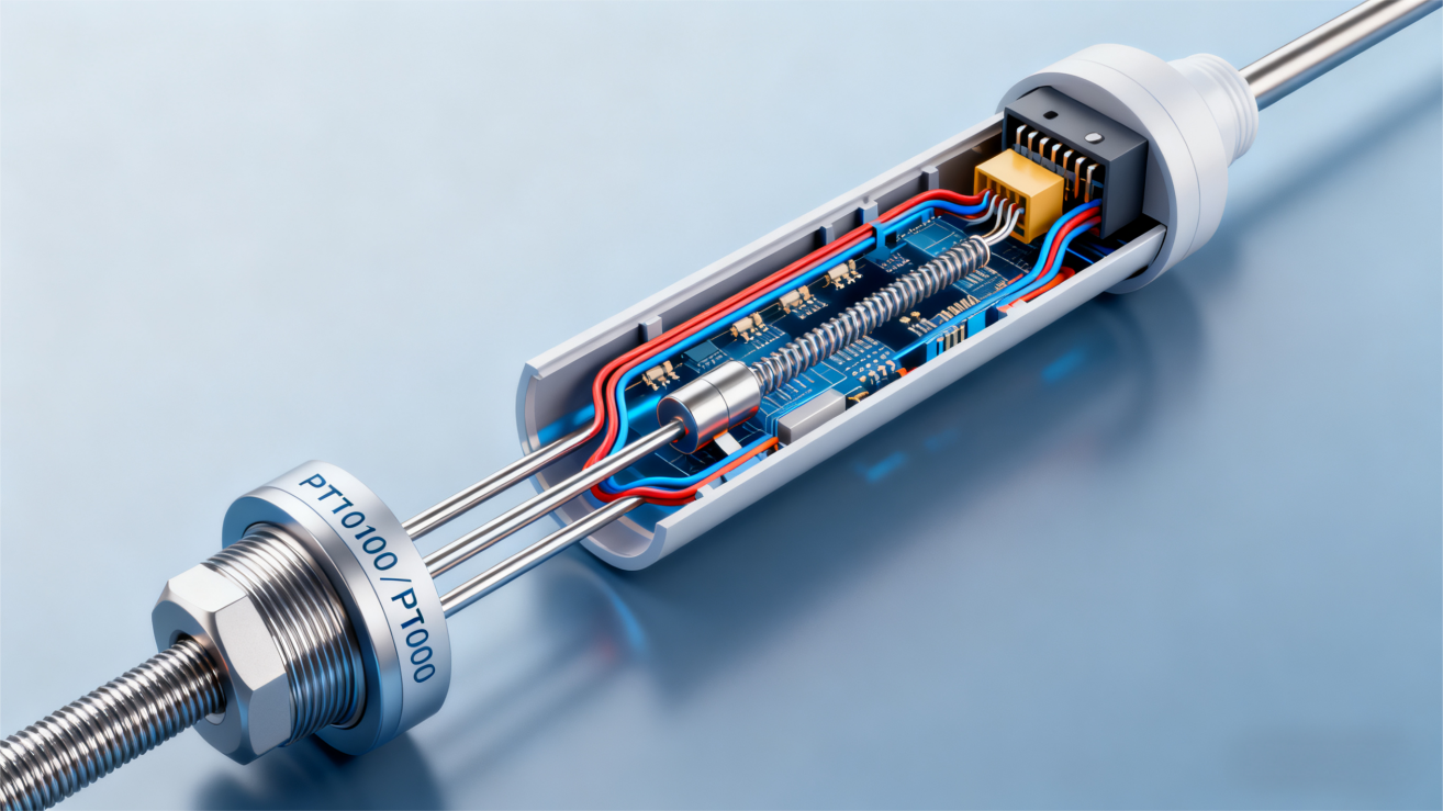
The image below is retained from the original article and is illustrative only; use an approved drawing to define a production sensor.
Related RTD selection resources
Review our RTD sensor assemblies, the two-wire and three-wire RTD example, and our RTD versus thermocouple selection guide. For project-specific questions, contact the team with your requirements.