
Heat meters combine flow information with the temperature difference between the flow and return sides of a heating or cooling circuit. Temperature sensors provide those readings to the meter calculator; the sensor type, installation and wiring must match the meter’s documented configuration.
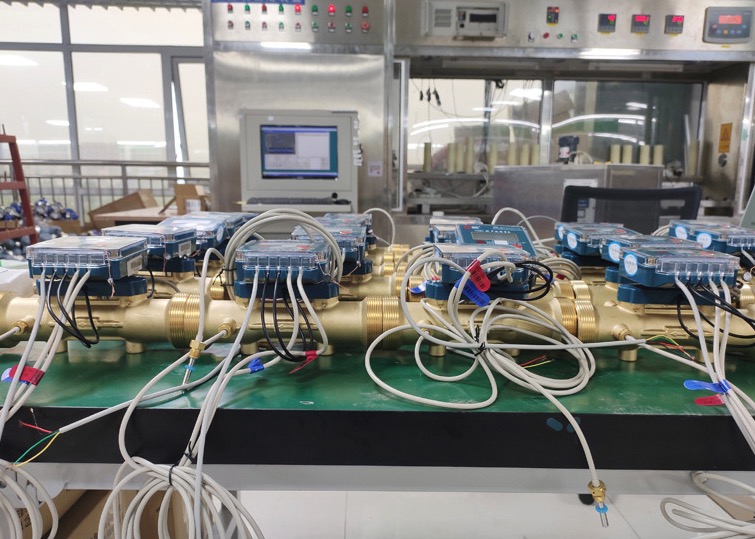
How temperature sensors work in a heat meter
A typical heat meter uses a flow sensor, a temperature-sensor pair and a calculator. One temperature probe is installed at the designated flow point and the other at the return point. The calculator combines their readings with the flow measurement and the heat-conveying liquid data specified for the meter.
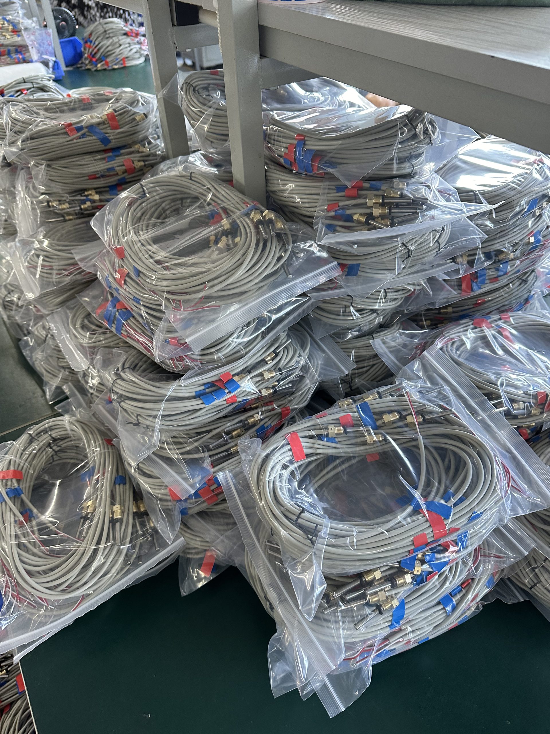
OIML R 75 describes heat calculation using the time-integrated mass flow and enthalpy difference; a volume-based approach uses a heat coefficient based on liquid properties. Actual calculation, sensor pair and approval requirements depend on the meter design and target market. See the OIML R 75 heat meter recommendation for technical background and confirm applicable requirements with the meter manufacturer.
PT1000 RTDs and pair compatibility
A PT1000 is a platinum resistance temperature detector with a nominal resistance of 1000 Ω at 0°C under its specified resistance-temperature curve. The meter must support the exact sensor curve and wiring arrangement. A sensor designation alone does not confirm compatibility or regulatory approval.
Some heat meter designs specify a temperature-sensor pair with defined matching criteria. Confirm how the meter supplier defines pair matching, the measurement range, wiring, lead resistance, calculator input and required inspection records. Do not assume that an individual probe tolerance automatically describes the performance of the complete pair or meter system.
Selection and installation checks
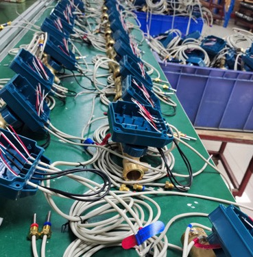
- Confirm the meter model, supported sensor curve, pair specification and calculator input.
- Check flow and return measurement locations, immersion depth or pocket arrangement, and installation orientation against the meter manual.
- Specify probe dimensions, mounting thread, cable routing, connector and wiring from the approved drawing.
- Describe the heat-conveying liquid, temperature range, pressure, flow conditions and environmental exposure for the complete assembly review.
- Agree on pair verification, traceability and acceptance records before production.
Install sensors only as instructed by the meter supplier. Validate both probes and the calculator together using the meter’s approved procedure, and record the test conditions, reference method and wiring so the result is repeatable.
Prepare an OEM inquiry
Provide the meter type or model, flow and return points, approved sensor input, pair-matching criteria, temperature range, probe or thermowell dimensions, cable and connector details, operating liquid and pressure conditions, quantity, drawing or sample reference, and required calibration or traceability records.
Review the paired PT1000 RTD sensor for heat meters, browse the PT100 and PT1000 RTD range, or request a heat meter sensor quotation. For a focused selection discussion, see our PT1000 heat meter matched-pair guide.
Summary
Heat meter temperature sensors need to match the meter’s sensor curve, pair criteria, installation and calculator input. Confirm the complete configuration and verification method with the meter manufacturer before selecting a PT1000 probe for production.


