Is an Infrared Thermocouple a Separate Sensor Type?
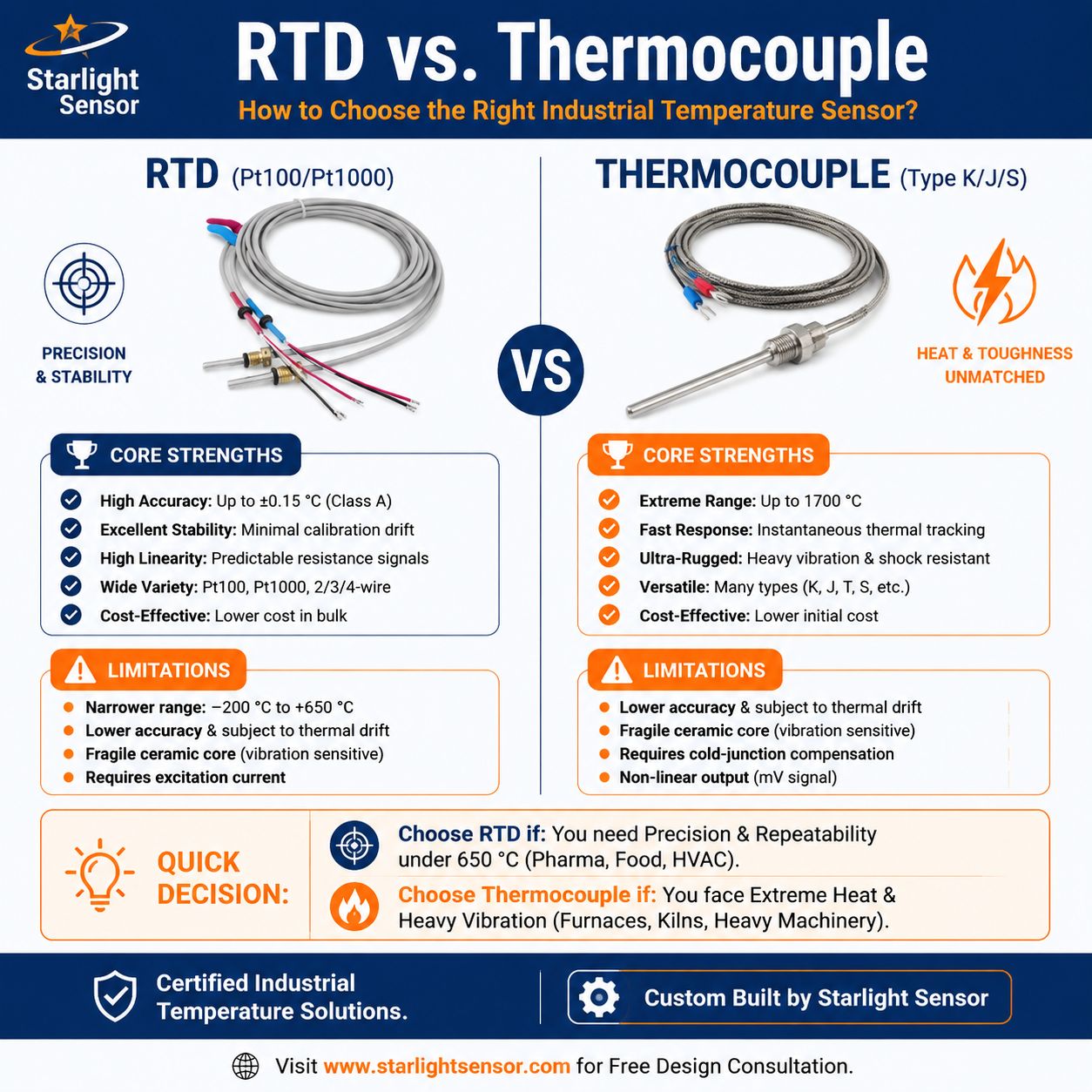
The phrase “infrared thermocouple” is often used when searching for non-contact temperature measurement, but the two technologies work differently. An infrared (IR) thermometer or radiation pyrometer estimates a target’s surface temperature from detected infrared radiation. A thermocouple is a contact sensor made from two dissimilar conductors that produce a Seebeck voltage related to the temperature difference across its junctions. If you need an IR device, search and specify an infrared temperature sensor or radiation thermometer; if you need a probe that touches the process, specify a thermocouple assembly.
For the contact method, see our thermocouple sensor range and RTD versus thermocouple selection guide.
How Infrared Temperature Measurement Works
An IR instrument’s optics collect radiation from a defined field of view. The detector and instrument electronics convert that signal into a temperature estimate using the instrument’s spectral response and emissivity settings. The instrument measures a surface, not the internal temperature of a part. The result depends on the target filling the measured field of view and on the surface, optical path, and ambient conditions.
“Infrared thermocouple” should not be taken to mean that every IR thermometer contains a thermocouple. Many instruments use thermopile detectors or other detector designs; verify the actual sensor and output architecture in the model’s datasheet. Likewise, do not apply an IR thermometer’s range, accuracy, or response figures to a different model.
IR Sensor vs. Contact Thermocouple
- Measurement: IR instruments read radiation from a surface without contact; thermocouple junctions measure temperature through thermal contact.
- Installation: IR measurement requires a clear optical path, known viewing geometry, and a target large enough for the measurement spot. A thermocouple requires an appropriate mounting or insertion point and thermal contact.
- Key error sources: IR readings can be affected by emissivity mismatch, reflections, target size, window transmission, dust, steam, or other obstructions. Thermocouple readings depend on junction placement, thermal coupling, extension-wire type, reference-junction compensation, and electrical noise.
- Use case: Consider IR when contact is impractical or a surface must be monitored from a distance. Consider a contact probe when the process requires an immersed, inserted, or attached measurement and the assembly can be installed safely.
IR Sensor Selection Checklist
- Target and surface: Identify material, finish, coating, expected emissivity, target dimensions, and whether the target moves or changes during operation.
- Viewing geometry: Specify working distance, field of view, distance-to-spot ratio (D:S), and alignment tolerance. Ensure the target fills the instrument’s measurement spot at the actual distance.
- Measurement conditions: State the required temperature span, ambient temperature, nearby heat sources, vibration, dust, steam, windows, and access constraints.
- Instrument data: Confirm spectral band, emissivity adjustment, response time, accuracy conditions, output type, supply, mounting, and calibration method in the exact model documentation.
- Controller integration: Match the output and wiring to the receiving input, and define scaling, alarm behavior, and fault handling.
Setup, Validation, and Calibration
Set emissivity according to the target surface and instrument instructions. Shiny metals can be challenging because reflected radiation can affect the reading. Check the instrument’s field of view and D:S documentation; a laser pointer may indicate aim but does not necessarily show the full measurement spot. If a window or protective barrier is used, verify its transmission for the instrument’s spectral band.
Validate the complete measurement setup at representative distances, target sizes, surface conditions, and ambient conditions. Compare against a suitable reference under the same geometry and document the uncertainty and acceptance criteria. Fluke’s IR thermometer calibration guide explains emissivity and size-of-source effects. For contact thermocouples, NIST’s thermocouple calibration publication describes thermoelectric measurement principles.
Prepare an OEM Inquiry
Share the target material and surface finish, temperature span, target size, measurement distance, optical path, ambient conditions, required output and supply, controller input, mounting constraints, response needs, calibration plan, sample quantity, and expected production volume. Identify whether you need a non-contact IR instrument or a contact thermocouple probe so the supplier can assess the correct measurement approach. Request an OEM quotation with a drawing and application details; confirm the selected model’s final performance from its datasheet and validation results.