Node-RED can collect and route temperature readings when a compatible sensor is connected through a suitable controller, gateway, or interface. The sensor does not connect to Node-RED by itself: confirm the complete measurement path from probe and wiring to acquisition hardware, data format, and flow before selecting a sensor.
Plan the measurement path
Start with the measurement point and operating range, then identify the acquisition device that will expose readings to Node-RED. Depending on the hardware, data may arrive through a digital bus, serial connection, industrial controller, or a gateway publishing messages over a network. Check the interface documentation for supported electrical levels, protocol, sample rate, and channel count. Node-RED flow nodes and network connectivity do not replace the sensor interface or electrical protection.
Choose a sensor that matches the interface
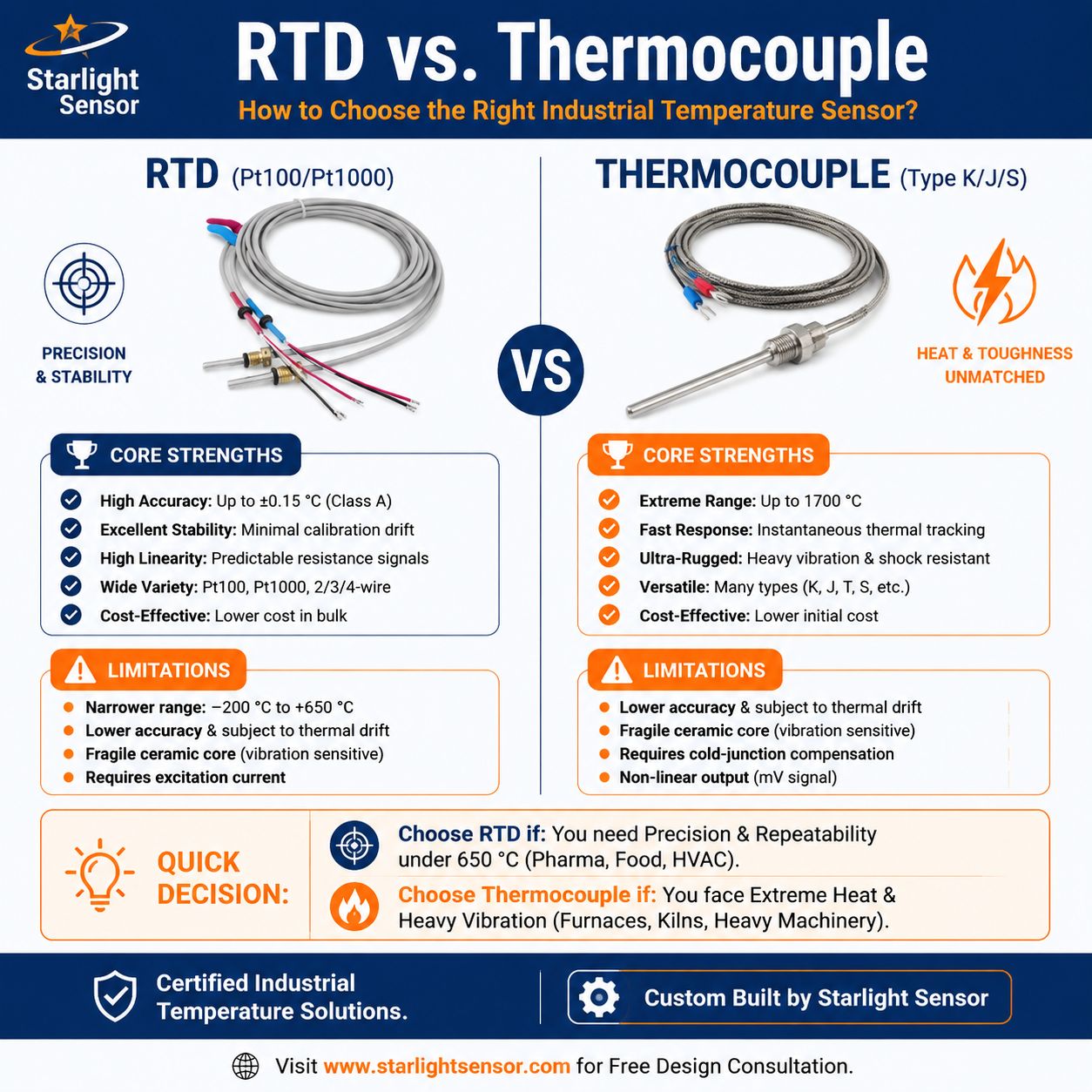
Specify the sensing element and finished probe together. For an NTC thermistor, define nominal resistance, B-value reference temperatures, curve tolerance, and the controller’s conversion method. For an RTD, define Pt100 or Pt1000, wiring configuration, excitation, and the compatible input module. For a thermocouple, identify the type, extension wiring, input module, and cold-junction compensation method. Do not assume these sensor families are interchangeable or that a generic Node-RED flow establishes compatibility.
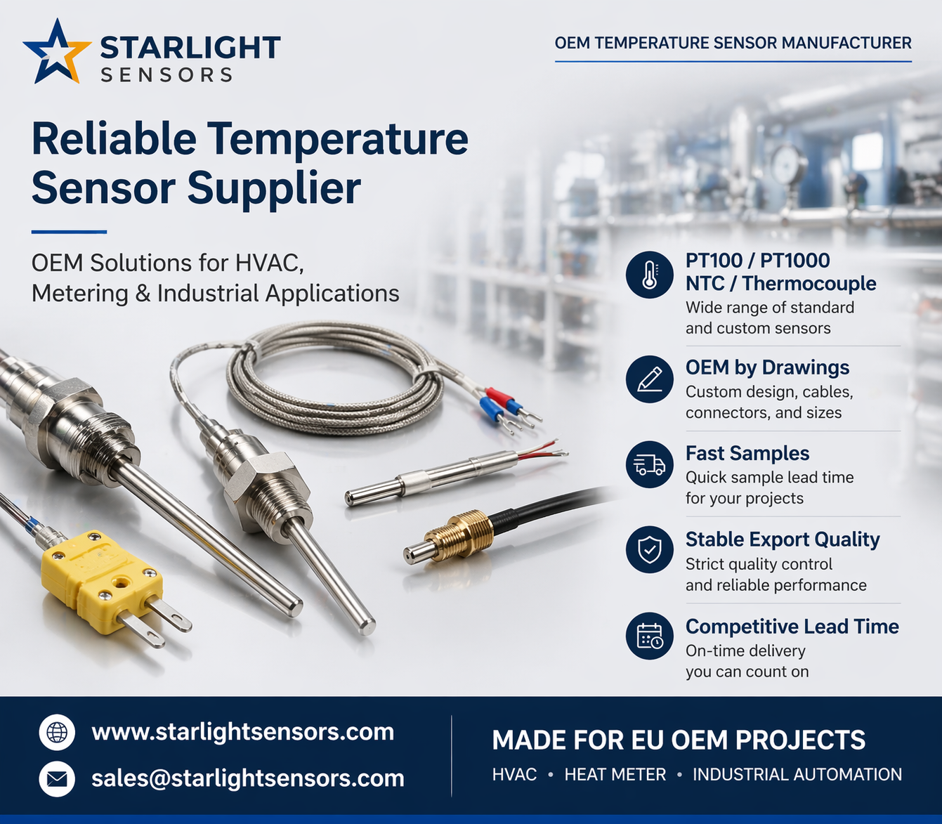
For OEM probes, also document sheath material and dimensions, cable and connector, mounting, response requirements, and exposure to moisture, chemicals, vibration, or washdown. Verify the complete assembled sensor with the selected acquisition hardware at representative operating points.
Build and validate a reliable Node-RED flow
- Read a timestamped value from the documented controller or gateway interface.
- Validate the payload, units, sensor status, and expected measurement range before using it.
- Handle missing, stale, or out-of-range readings explicitly; do not silently treat communication failures as valid temperatures.
- Record a known test input and compare the displayed value with a reference instrument across the required range.
- Document sampling interval, filtering, scaling, alarm thresholds, and recovery behavior for the deployed flow.
OEM temperature sensor RFQ checklist
- Measurement range, accuracy requirement, and calibration points.
- Sensor type, resistance curve or thermocouple type, and controller/interface model.
- Probe dimensions, mounting, cable length, connector, and environmental conditions.
- Data protocol, sampling interval, units, and expected failure handling.
- Drawing revision, sample quantity, production volume, and inspection requirements.
Discuss a custom probe
Review the available temperature sensor options and include your controller or gateway model when you contact Starlight about an OEM probe. Interface compatibility, electrical limits, curve data, and assembly details should be confirmed for the selected model before design-in.