A return air temperature sensor measures air flowing back toward an HVAC unit or air-handling equipment. Its signal can inform a controller, but sensor selection alone does not determine indoor air quality, system efficiency, or control performance. Engineers should match the sensing element, electrical input, installation location, and completed assembly to the specific HVAC design.
How to Choose a Return Air Temperature Sensor
Start with the controlled variable and the equipment drawing. Identify whether the sensor belongs in a return duct, plenum, unit inlet, or another defined point. Confirm that the air is representative of the condition the controller is intended to use. Airflow mixing, nearby heat sources, leakage, stagnant pockets, and contact with a cold surface can all affect the local reading. Verify placement against the actual duct layout and service access.
Match the sensor to the controller input
Specify the input type before selecting a probe. For an NTC thermistor input, provide the required reference resistance and temperature, resistance–temperature (R/T) curve, tolerance, excitation or readout circuit, and conversion method. A nominal resistance or beta value alone does not establish controller compatibility across the full operating span. TDK’s NTC technical information explains R/T characteristics, beta values, tolerances, and self-heating; apply the exact curve and limits supplied for the selected part.
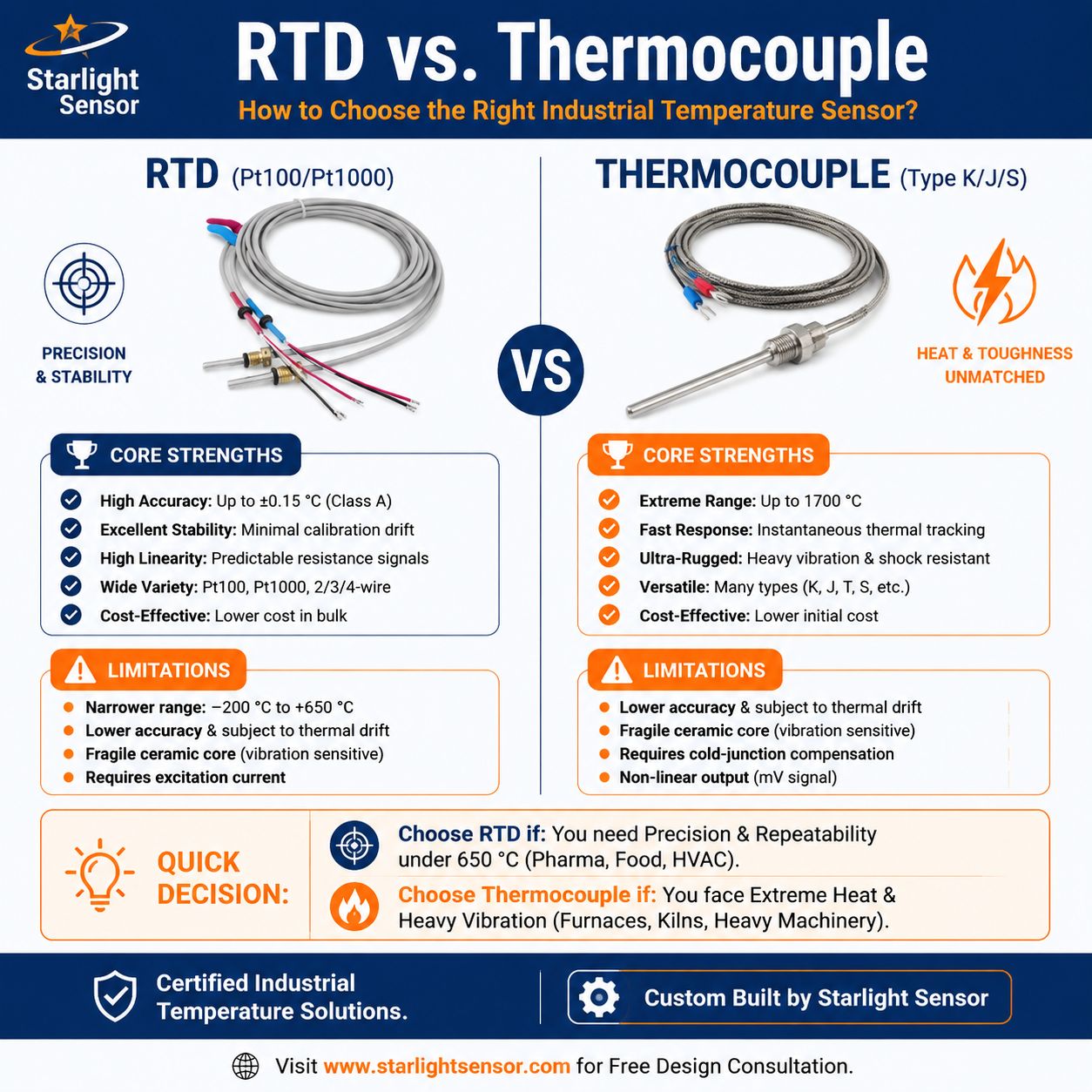
If the controller is designed for an RTD or thermocouple, confirm the specific sensor type, wiring arrangement, input range, and required conversion at the controller. Do not substitute one technology for another based only on the application name. Check the complete sensor, cable, connector, controller, and software chain at representative operating points.
Specify the probe and installation
Define the probe diameter and insertion length, mounting clip or fitting, enclosure, cable type and length, connector, strain relief, and service access. Document airflow, vibration, condensation, dust, cleaning agents, and ambient exposure. Confirm that the sensing tip sits in the intended air stream without unwanted contact with the duct wall. The mounting method and thermal path can affect response and the value seen by the controller, so include the installation drawing in the review.
Commission and validate the measurement
Before release, confirm that the controller displays a plausible value and responds correctly to a known change in temperature. Compare the installed sensor and readout with a suitable reference at stable points across the required range. Allow readings to settle, record the test location and conditions, and check for wiring, configuration, or conversion errors. Document acceptance criteria and repeat the check after any change to the probe, controller settings, cable, or mounting.
Return air temperature sensor RFQ checklist
- HVAC equipment, controller model or input type, and the required sensor technology.
- Return duct or plenum position, airflow conditions, insertion depth, and mounting drawing.
- For NTC: part number, reference resistance and temperature, R/T curve or beta interval, and tolerance.
- Required system accuracy, response requirement, verification method, and sampling needs.
- Probe dimensions and materials, cable, connector, strain relief, condensation, vibration, and service conditions.
- Sample quantity, drawing revision, validation criteria, and expected production volume.
Review an HVAC temperature probe option
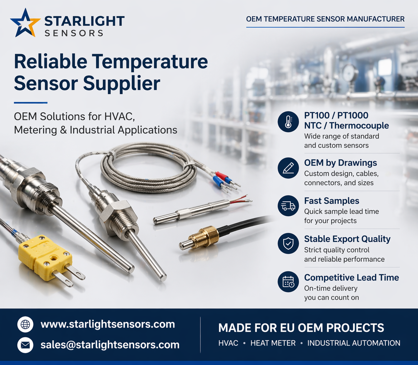
Starlight’s air-conditioner temperature sensor is an example of an NTC-based HVAC sensing product. Confirm its current resistance curve, construction, dimensions, cable, and environmental limits before applying it as a return-air sensor. For a different controller or custom mounting, request an OEM review with the controller input, operating conditions, drawing, cable, and connector requirements.
Frequently asked questions
Is return-air temperature the same as room temperature?
Not necessarily. A return-air reading represents air at the installed sensor location and can differ from a room reading because of airflow, mixing, duct conditions, and sensor placement. Define the required measurement point in the control design.
Can any NTC return-air probe work with my controller?
No. The controller must support the probe’s resistance curve and electrical interface. Confirm the exact part data and validate the assembled sensor-controller system before production use.