Start With the Measurement Task
“Temperature measuring instruments” can refer to contact sensors, instruments that read a sensor, or non-contact thermometers. For an industrial OEM, specify the measurand, operating range, response requirement, environment, controller interface and validation method before choosing a device. A sensor’s nominal element accuracy does not by itself describe the performance of the installed measurement system.
Match the Technology to the Application
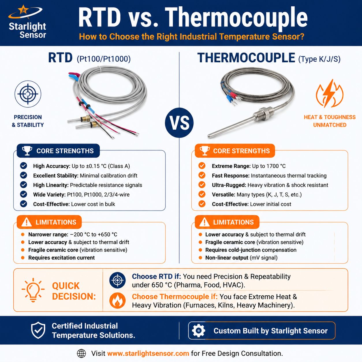
- Thermocouples: Two dissimilar conductors produce a temperature-related voltage. Select the thermocouple type, junction, insulation, sheath and lead arrangement for the process and input instrument. Cold-junction compensation and extension wiring matter to the complete measurement.
- RTDs: Platinum resistance detectors suit applications where the specified resistance curve, tolerance class, wiring method and operating conditions meet the system requirements. Check the sensor, lead resistance, excitation, input circuit and calibration together.
- NTC thermistors: Their nonlinear resistance–temperature curve can provide useful sensitivity over a selected range. Choose by the exact R/T data, tolerance, beta interval, self-heating and assembly construction rather than nominal resistance alone.
- Infrared thermometers: These infer surface temperature from emitted radiation without contact. Emissivity, field of view, target size, distance and intervening materials affect readings. They measure a different measurand from an immersed or attached contact probe.
Explore our thermocouple sensors, RTD sensors, NTC sensors and temperature sensor range to compare OEM probe options.
Define System-Level Requirements
Document the normal and excursion temperatures; process medium and pressure; immersion or contact depth; mounting location; vibration, moisture and chemical exposure; cable routing; connector; controller input; and maintenance access. Include the expected thermal lag and acceptable measurement error. A response-time value or range should come from the selected assembly’s documented test conditions, not from a generic sensor category.
For multi-point or continuous monitoring, specify channel count, sampling interval, data handling and alarm logic separately from the sensing element. Confirm how the instrument handles open circuits, out-of-range inputs and sensor replacement.
Install, Calibrate and Validate
Place a contact sensor where it represents the process temperature, with suitable thermal coupling and insertion depth. For infrared measurement, ensure the target fills the instrument’s field of view and use a validated emissivity setting. Compare the complete sensor, wiring and readout against a suitable reference at stable points across the required span. Record the reference, test conditions, uncertainty, acceptance limits and calibration interval determined for the application.
For thermocouple systems, see NIST’s thermocouple calibration guidance. For infrared instruments, Fluke explains IR thermometer calibration considerations. Follow the calibration procedure applicable to the actual instrument and use case.
Prepare an OEM Request for Quote
Send a drawing and specify the target point, sensor technology or required input, range, tolerance or system error target, probe dimensions, sheath and insulation materials, cable and connector, process conditions, sample quantity and annual volume. Ask the supplier to confirm the applicable datasheet, test conditions, calibration documentation and any limits that depend on the finished assembly. Request an OEM quotation with these details to support a focused review.