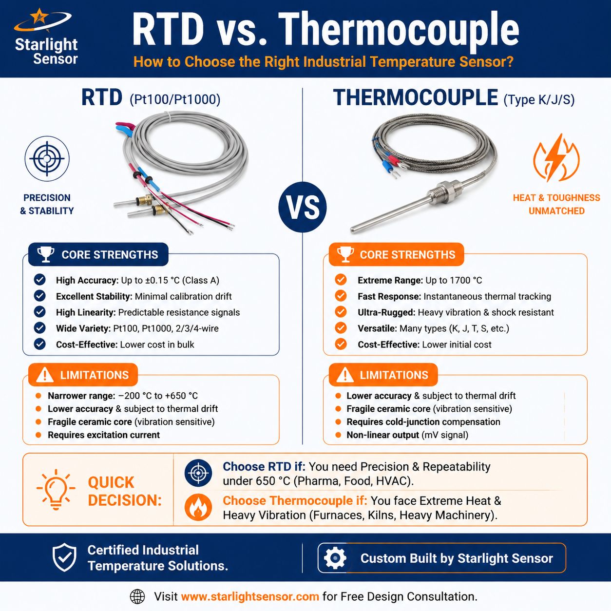
Platinum resistance temperature detectors (RTDs) can be considered in medical equipment when the design calls for a resistance-based temperature input. The correct sensor depends on the device’s intended measurement, operating conditions, electronics, construction, and validation plan. A sensor by itself does not establish clinical suitability, patient safety, device accuracy, or regulatory compliance.
This article is for equipment engineers and OEM teams specifying a temperature-sensing component. Any use in a regulated or patient-connected device must be assessed by the device manufacturer within its applicable risk-management, verification, and regulatory processes.
Define what the device must measure
Begin with the measurement objective and physical location: air, liquid, a surface, a component, or another defined point. Record normal and fault conditions, ambient temperature, moisture, cleaning or disinfection exposure, vibration, expected thermal cycling, response needs, and whether the sensor contacts the patient or a patient-contacting medium. These details guide the mechanical construction and test plan.
Separate the sensor requirement from the system requirement. The reported temperature also depends on placement, thermal contact, lead routing, signal conditioning, conversion logic, controller configuration, and software. Define acceptance limits for the complete channel in the intended installation rather than assuming that an element tolerance alone describes device-level performance.
Match the RTD to the electronics
Specify the nominal resistance, reference temperature, resistance–temperature curve or standard, tolerance, wiring method, and excitation or measurement approach. Confirm the receiving circuit supports the selected element and lead configuration. Two-wire, three-wire, and four-wire arrangements differ in how lead resistance is treated, and the actual cable and connector transitions should be included in the design review.
Evaluate whether self-heating, electrical noise, isolation, grounding, and input filtering matter in the device’s circuit. These are system-design questions: the sensor supplier’s drawing or test data should identify the assembly details but cannot replace verification of the host electronics.
Review construction, integration, and lifecycle
Document the probe dimensions, sheath and insulation materials, sealing method, cable jacket, strain relief, connector, and routing. Confirm mechanical fit, cleanability, service access, and any material restrictions with the device design team. For a sensor that is patient-adjacent or used in a critical control loop, the responsible manufacturer must determine the required evidence and perform the applicable assessment.
During sourcing, agree how the approved drawing, bill of materials, inspection records, calibration evidence (if needed), lot identification, and engineering changes will be controlled. Define how samples will be evaluated and what constitutes acceptance before production release. Do not infer a supplier’s medical-device qualification or certification from a general sensor listing.
Plan verification for the complete channel
Test the sensor with the intended cable, connector, acquisition electronics, software scaling, mounting, and thermal environment. Select reference points that represent actual use and record the reference method, stabilization, uncertainty, sensor location, and instrument settings. If the application requires calibration, define the range, points, acceptance criteria, records, and recalibration policy within the quality system.
Risk analysis and regulatory obligations belong to the medical-device manufacturer and its qualified specialists. Component data can support that review, but a temperature probe alone is not evidence that the finished device is safe or compliant.
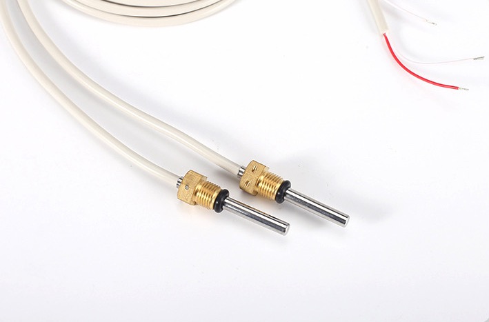
The original article image is retained as an illustration; it does not depict or certify a particular medical sensor assembly.
OEM information checklist
- intended measurement and sensor location;
- operating, excursion, and ambient conditions;
- RTD element, curve, tolerance, wiring, and input circuit;
- probe dimensions, materials, sealing, cable, and connector;
- verification method, acceptance criteria, and required records;
- approved drawing revision, lot traceability, and change-control requirements.
For component context, see our RTD sensor assemblies and PT100/PT1000 sensor example. To discuss dimensions and interfaces for an OEM application, submit a project inquiry.