A flue gas temperature sensor measures temperature at a defined point in an exhaust or flue path. It does not by itself optimize combustion or establish safe operating limits. Probe location, gas flow, deposits, materials, instrument input, and the system’s approved combustion controls all affect the reading and its use.
Define the flue measurement point
Provide the stack or duct layout, gas flow direction, expected temperature profile, insertion depth, and the reason for the measurement. Consider gradients across the duct, proximity to bends or equipment outlets, vibration, draft, and maintenance access. The selected location should be reviewed with the responsible process or combustion-system designer.
Match the sensor and readout
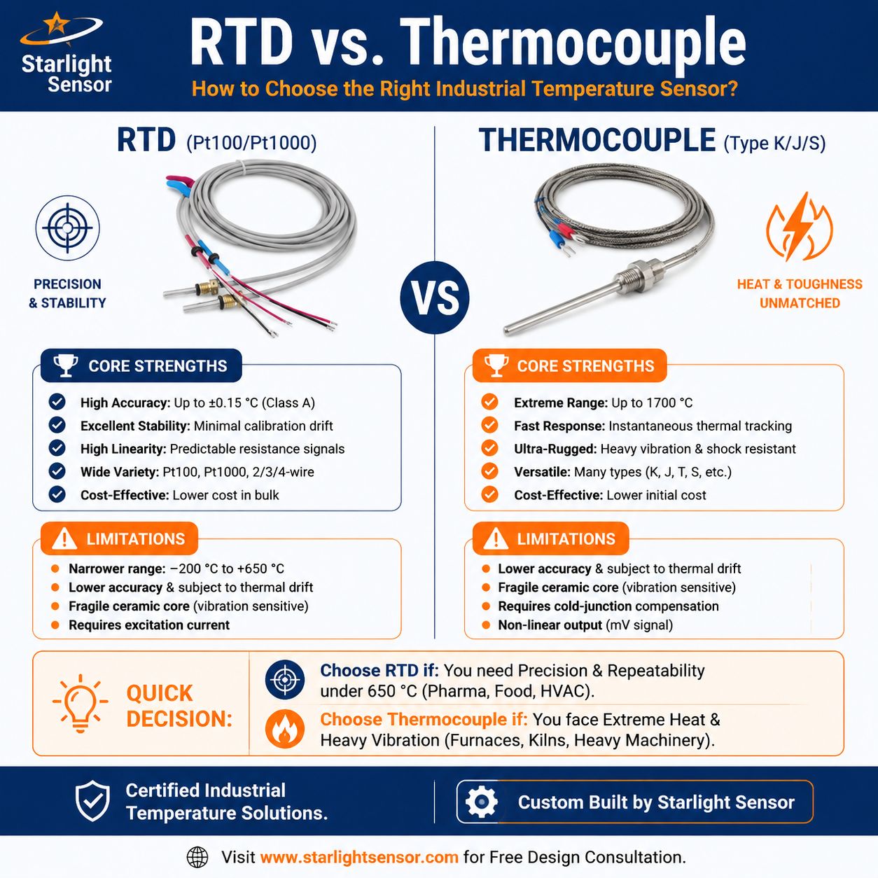
Specify the thermocouple type or RTD/thermistor curve, instrument input, wiring, compensation or excitation, calibration, and required response. Confirm the instrument uses the same sensor type as the installed probe. Define whether the measurement supports trending, a display, alarm, or a control function; integration into safety or combustion control must follow the system’s approved design.
Select construction for exhaust conditions
Document normal, peak, and cycling temperatures, gas composition, condensate, soot or particulates, corrosion, pressure, flow, vibration, and cleaning method. Specify sheath material and dimensions, junction, insertion length, mounting, sealing, cable, and connector. Do not infer a safe temperature or chemical limit from “flue sensor” alone; verify the complete assembly for the actual gas and installation.
Validate the installation and trend
Check sensor placement, wiring, input configuration, and readings against a reference or commissioning procedure. Establish inspection intervals for deposits, corrosion, sheath wear, and drift. Document how the system identifies disconnected, stale, or implausible readings and who is responsible for interpreting them.
Flue temperature probe RFQ checklist
- Duct/stack drawing, gas flow, measurement purpose, location, and insertion depth.
- Temperature profile, gas/condensate composition, deposits, pressure, and cycling.
- Sensor type, input model, wiring/compensation, response, calibration, and alarm use.
- Sheath, junction, mounting, seal, cable, connector, and maintenance access.
- Drawing revision, sample quantity, production volume, inspection, and system approvals.
Review flue gas probe options
See the gas temperature sensor probe guide and review the thermocouple sensor range. Include the gas conditions, duct layout, and controller model when you request an OEM review; confirm model-specific materials, limits, and installation requirements.