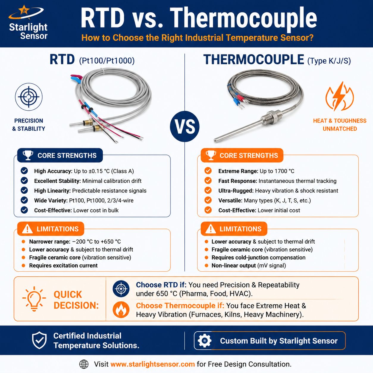
RTD sensors can provide temperature input to new energy equipment when the sensing element, installation, and receiving electronics are designed for the application. Examples of equipment may include motor systems, power conversion assemblies, thermal-management equipment, and production machinery. The appropriate location and sensor construction depend on the equipment design and the quantity that must be monitored.
A temperature sensor contributes measurement data; it does not by itself prevent overheating, protect a battery, or establish equipment safety. Control and protection depend on the complete sensor, wiring, input, logic, alarm or trip function, and validated system design.
Define the equipment and measurement objective
Identify the component and physical location to be measured, such as a winding, bearing area, enclosure, coolant line, or other defined point. Record the expected temperature profile, excursions, ambient conditions, vibration, electromagnetic environment, moisture or chemicals, installation access, and service life. Avoid treating motor, inverter, battery, and cooling-loop measurements as interchangeable; each may require a different mounting approach and response.
Clarify whether the RTD feeds an indicator, process controller, data logger, or protective relay. The equipment designer should define alarms, limits, fail-safe behavior, and independent safeguards as appropriate. A sensor’s tolerance does not equal the complete measurement channel’s uncertainty or the equipment’s protection capability.
Match the RTD element and input circuit
Specify the nominal resistance, reference temperature, resistance–temperature curve or standard, element tolerance, wiring arrangement, cable, connector, and controller input. Confirm that the receiving instrument is configured for the chosen RTD curve and lead scheme. Two-, three-, and four-wire circuits treat lead resistance differently; include the actual cable length and connection method in the review.
Check excitation and input design for the intended circuit, including self-heating, noise, grounding, shielding, isolation, and filtering where relevant. Evaluate the sensor together with the cable, connector, input hardware, and software scaling. Do not infer an accuracy or operating-temperature range from the generic RTD name alone.
Specify mechanical integration
Describe the sheath or probe material, dimensions, insertion length, mounting method, sealing, strain relief, cable routing, connector, and clearance. For winding or embedded measurements, provide the mechanical drawing and assembly method; for pipe or coolant measurements, define contact, insertion, or thermowell details as applicable to the equipment. Verify that thermal contact, insulation, electrical isolation, and service access meet the system design.
Check environmental qualification against the actual assembly and its installation. A sensor part number or product photograph alone does not demonstrate vibration resistance, ingress protection, electromagnetic compatibility, or suitability for a particular vehicle or power system.
Plan verification and change control
Agree on sample acceptance before production: for example, dimensional fit, wiring/pinout, resistance at specified points, installation inspection, and representative thermal response checks where required. Define reference method, test conditions, acceptance limits, and records. Validate the installed channel across the relevant operating states and include the instrument and software conversion in the results.
Keep the approved drawing and revision, element and material details, inspection evidence, lot identification, and supplier change-notification requirements aligned with the purchase specification. Decide which team approves substitutions and how changes are revalidated.
The image below is retained from the original page and is illustrative only; it is not an electrical or mechanical specification.

OEM information checklist
- equipment component and exact measurement point;
- temperature profile, environment, vibration, and service conditions;
- RTD resistance curve, tolerance, wiring, cable, and input instrument;
- probe construction, dimensions, mounting, sealing, and connector;
- sample validation, acceptance criteria, traceability, and change control;
- monitoring or protective function assigned to the complete equipment system.
For a relevant assembly example, review our two-wire and three-wire RTD sensor for new energy equipment and the broader RTD sensor range. See also our transformer monitoring guide and OEM RTD specification checklist. Contact the team with your drawing and application details for a project-specific review.