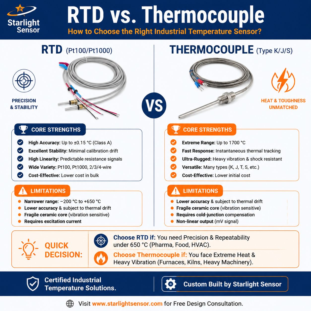
A Pt500 RTD sensor is a platinum resistance temperature detector with a nominal resistance of 500 Ω at 0 °C, as defined in WIKA’s terminology reference. Its resistance changes with temperature; a compatible instrument or transmitter converts that input into a usable measurement. Pt500 is not an NTC thermistor, and the two technologies must not be treated as interchangeable.
Pt500 RTD and NTC thermistor: different sensor inputs
Both Pt500 RTDs and NTC thermistors are resistance-based temperature sensors, but they use different materials and resistance-temperature characteristics. A controller or transmitter configured for one type may not measure the other correctly. Confirm the sensor profile supported by the receiving device and use the characteristic curve and limits in the selected sensor’s data sheet.
Pt500 identifies the nominal resistance class; it does not by itself specify the probe’s temperature range, tolerance, response, construction, cable or process suitability. Those details depend on the actual sensor design and manufacturer documentation. For comparison, see our NTC temperature sensor category and Pt100 and 4–20 mA transmitter selection guide.

What to verify when selecting a Pt500 probe
- Measurement range: confirm that the sensor and connected instrument cover the required process temperatures.
- Input configuration: check that the controller, meter or transmitter explicitly supports Pt500 and the intended wiring arrangement.
- Tolerance and calibration: review the data sheet and any project calibration requirement; do not infer accuracy from the Pt500 designation alone.
- Probe and mounting: specify sheath or probe dimensions, insertion depth, mounting, process contact and environmental exposure.
- Lead and connection: confirm cable length, conductor arrangement, connector and installation routing against the instrument requirements.
- Signal conditioning: where a standard output is required, verify that the chosen transmitter accepts Pt500 and that its configured output and receiving scale match.

System integration and validation
Plan the sensor, wiring, transmitter and receiving controller as one measurement path. Follow the device maker’s wiring diagram, check the configured sensor type and range, and validate the assembled system at representative operating points against an appropriate reference. Record the chosen input profile, scaling, installation details and any fault behavior required by the application.
For broader selection context, review our RTD vs. thermocouple guide and RTD temperature sensor range. The product category is general; confirm availability and exact Pt500 configurations for a specific project rather than assuming a model is offered.
Information to include in an OEM inquiry
Share the target temperature range, process medium and environment, Pt500 input and wiring requirements, probe dimensions and mounting, cable and connector details, instrument or transmitter input, desired output, and any drawing or sample. This gives the engineering team a clear basis to review the sensing element and assembly requirements.
Contact Starlight Sensors to discuss an OEM temperature-sensing project or request a quote.
Reference: WIKA FAQ on RTD and Pt-value terminology. The reference explains the Pt500 designation; it does not represent Starlight’s product availability.